
如何使用STM32Cube库创建I2C从设备
如何使用STM32Cube Library1创建I2C从设备。简介在本文中,我们将了解如何使用STM32CubeMX和STM32CubeHAL库创建带有中断的I2C从设备。所有I2C从通信将被处理。。。
How to create an I2C slave device using the STM32Cube Library
1. Introduction
In this article we will see how to create an I2C slave device with interrupts using the STM32CubeMX and STM32Cube HAL Library. All the I2C slave communication will be handled by firmware.2. Pre-requisite
- Hardware:
- Micro USB cable: to power and program the board
- Nucleo-G070RB board
- Software
- STM32CubeIDE
3. Theory
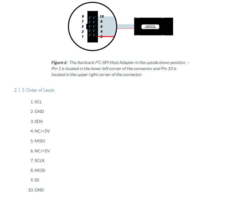
Adding an I2C slave to an application can be a bit tricky due to the complexity of the I2C protocol. In this article we will show you how to add asynchronous I2C slave code using the STM32cubeIDE tool for I2C configuration and then include the necessary code to handle the I2C slave asynchronous mode using interrupts. For this article, a Total Phase Aardvark is used as the I2C master.

The pinout of the Aardvark:
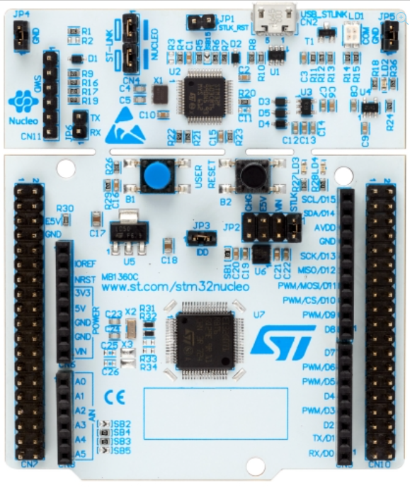
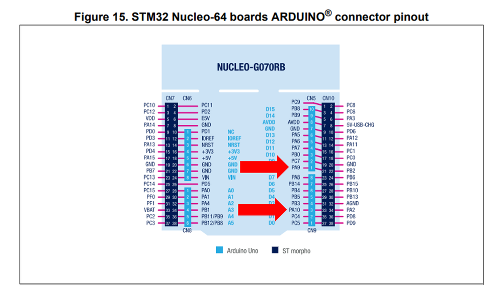
Nucleo-G070RB:
- PA9 and PA10 of the STM32G070 on the Nucleo-G070RB will be used for the I2C communication.
Connections:
- NUCLEO-G070RB Set-up:
- Connect the SCL line of Master Aardvark to I2C_SDA line of the Nucleo Slave Board (PA9: pin 21 of CN10).
- Connect the SDA line of Master Aardvark to I2C_SDA line of the Nucleo Slave Board (PA10: pin 33 of CN10).
- Connect GND of Aardvark board to GND of Nucleo Board.
The software Control Center from Total Phase will be used to setup and control the master I2C communications with the STM32 I2C slave code.
4. Steps
- Open STM32CubeIDE
- Create a new project using the NUCLEO-G070RB board

- Enter a name for the project (in this case, the project is named I2CSlave).

- Board Project Options:
- Initialize all peripherals with their default settings by clicking on Yes when this dialog window appears:

- Select the I2C peripheral
- In Pinout & Configuration Tab, under Communication, click on I2C1 peripheral.

- Enable I2C mode and keep the default Timing Configuration

- Configure the Slave part by adding the I2C slave address
- For this example, 0x20 will be used as the I2C slave address. The rest of the default configuration is kept.

- Enable I2C1 interrupts
- As mentioned earlier, the I2C communications will be handled using Interrupts which is the most convenient and efficient way to handle slave communication.
- In NVIC tab enable the Interrupts as shown below:

5. Code generation
- Generate Code
- Saving the project generates the code
- Add code:
- Now that the I2C peripheral is configured using the STM32CubeIDE, now add some code to handle the I2C slave communication for both Transmit and Receive operations.
- In main.c, add the following code at the beginning of the file:
/* Private includes ----------------------------------------------------------*/
/* USER CODE BEGIN Includes */
#define COUNTOF(__BUFFER__)   (sizeof(__BUFFER__) / sizeof(*(__BUFFER__)))
/* Size of Transmission buffer */
#define TXBUFFERSIZE                      (COUNTOF(aTxBuffer))
/* Size of Reception buffer */
#define RXBUFFERSIZE                      TXBUFFERSIZE
/* USER CODE END Includes */

/* Private typedef -----------------------------------------------------------*/
/* USER CODE BEGIN PTD */
__IO uint32_t     Transfer_Direction = 0;
__IO uint32_t     Xfer_Complete = 0;
/* USER CODE END PTD */

/* Private define ------------------------------------------------------------*/
/* USER CODE BEGIN PD */
/* Buffer used for transmission */
uint8_t aTxBuffer[4];

/* Buffer used for reception */
uint8_t aRxBuffer[4];
/* USER CODE END PD */
- Add following code in the main function which initializes the receive and transmit buffers being used.
  /* USER CODE BEGIN Init */
  aRxBuffer[0]=0x00;
  aRxBuffer[1]=0x00;
  aRxBuffer[2]=0x00;
  aRxBuffer[3]=0x00;
  aTxBuffer[0]=0xAA;
  aTxBuffer[1]=0xBB;
  aTxBuffer[2]=0xCC;
  aTxBuffer[3]=0xDD;
  /* USER CODE END Init */
…
- Enable the Listen mode with Interrupts for the I2C: The Listen Mode will wait for an I2C Event to occur and will be treated in the Interrupt Service Routine of the I2C.
/* USER CODE BEGIN 2 */
  if(HAL_I2C_EnableListen_IT(&hi2c1) != HAL_OK)
  {
    /* Transfer error in reception process */
    Error_Handler();
  }
  /* USER CODE END 2 */
…
- Xfer_Complete variable will be updated in the call back function that will be added later. Basically, once a slave receive or transmit transaction is completed, the Listen mode Interrupt will be entered again.
/* USER CODE BEGIN WHILE */
  while (1)
  {

           if (Xfer_Complete ==1)
           {
            HAL_Delay(1);
             /*##- Put I2C peripheral in listen mode process ###########################*/
         if(HAL_I2C_EnableListen_IT(&hi2c1) != HAL_OK)
         {
           /* Transfer error in reception process */
           Error_Handler();
         }
           Xfer_Complete =0;
           }

    /* USER CODE END WHILE */

…


In these functions, the call back functions are added and manage the slave transmit or slave receive part of the code.

/* USER CODE BEGIN 4 */
/**
  * @brief  Tx Transfer completed callback.
  * @param  I2cHandle: I2C handle.
  * @note   This example shows a simple way to report end of IT Tx transfer, and
  *         you can add your own implementation.
  * @retval None
  */

void HAL_I2C_SlaveTxCpltCallback(I2C_HandleTypeDef *I2cHandle)
{
  /* Toggle LED4: Transfer in transmission process is correct */

  Xfer_Complete = 1;
  aTxBuffer[0]++;
  aTxBuffer[1]++;
  aTxBuffer[2]++;
  aTxBuffer[3]++;

}


/**
  * @brief  Rx Transfer completed callback.
  * @param  I2cHandle: I2C handle
  * @note   This example shows a simple way to report end of IT Rx transfer, and
  *         you can add your own implementation.
  * @retval None
  */
void HAL_I2C_SlaveRxCpltCallback(I2C_HandleTypeDef *I2cHandle)
{
  /* Toggle LED4: Transfer in reception process is correct */

  Xfer_Complete = 1;
  aRxBuffer[0]=0x00;
  aRxBuffer[1]=0x00;
  aRxBuffer[2]=0x00;
  aRxBuffer[3]=0x00;
}


/**
  * @brief  Slave Address Match callback.
  * @param  hi2c Pointer to a I2C_HandleTypeDef structure that contains
  *                the configuration information for the specified I2C.
  * @param  TransferDirection: Master request Transfer Direction (Write/Read), value of @ref I2C_XferOptions_definition
  * @param  AddrMatchCode: Address Match Code
  * @retval None
  */
void HAL_I2C_AddrCallback(I2C_HandleTypeDef *hi2c, uint8_t TransferDirection, uint16_t AddrMatchCode)
{
  Transfer_Direction = TransferDirection;
  if (Transfer_Direction != 0)
  {
     /*##- Start the transmission process #####################################*/
  /* While the I2C in reception process, user can transmit data through
     "aTxBuffer" buffer */
  if (HAL_I2C_Slave_Seq_Transmit_IT(&hi2c1, (uint8_t *)aTxBuffer, TXBUFFERSIZE, I2C_FIRST_AND_LAST_FRAME) != HAL_OK)

    {
    /* Transfer error in transmission process */
    Error_Handler();
  }

  }
  else
  {

      /*##- Put I2C peripheral in reception process ###########################*/
  if (HAL_I2C_Slave_Seq_Receive_IT(&hi2c1, (uint8_t *)aRxBuffer, RXBUFFERSIZE, I2C_FIRST_AND_LAST_FRAME) != HAL_OK)
    {
    /* Transfer error in reception process */
    Error_Handler();
  }

  }

}

/**
  * @brief  Listen Complete callback.
  * @param  hi2c Pointer to a I2C_HandleTypeDef structure that contains
  *                the configuration information for the specified I2C.
  * @retval None
  */
void HAL_I2C_ListenCpltCallback(I2C_HandleTypeDef *hi2c)
{
}

/**
  * @brief  I2C error callbacks.
  * @param  I2cHandle: I2C handle
  * @note   This example shows a simple way to report transfer error, and you can
  *         add your own implementation.
  * @retval None
  */
void HAL_I2C_ErrorCallback(I2C_HandleTypeDef *I2cHandle)
{
  /** Error_Handler() function is called when error occurs.
    * 1- When Slave doesn't acknowledge its address, Master restarts communication.
    * 2- When Master doesn't acknowledge the last data transferred, Slave doesn't care in this example.
    */
  if (HAL_I2C_GetError(I2cHandle) != HAL_I2C_ERROR_AF)
  {
    Error_Handler();
  }
}
/* USER CODE END 4 */
6. Project Build
Build the project, enter debug mode and run the code
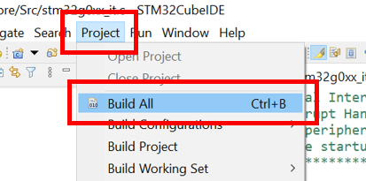
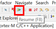
- Enter Debug session: this programs the code into the flash and then starts the debug session

- Then click on the Resume icon which will execute the code.
In the Total Phase Control Center software, connect to the Aardvark device. The Aardvark is configured to act as an I2C Master. We are testing our code for I2C slave transmit and receive by sending some I2C Master Reads and Writes as follows:
- Send a buffer of 4 bytes “01 02 03 04” two times (Master Write).
- Master read of 4 bytes three times (Master Read).

As shown in the Transaction Log, the STM32G0 I2C Slave code received and transmitted data as expected.
7. Links
STM32G070RB - Datasheet
STM32G0x0 advanced Arm®-based 32-bit MCUs - Reference manual
STM32CubeIDE - Integrated Development Environment for STM32 - STMicroelectronics
NUCLEO-G070RB - STM32 Nucleo-64 development board with STM32G070RB MCU, supports Arduino and ST morp...
Aardvark I2C/SPI Host Adapter - Total Phase
Total Phase Control Center